
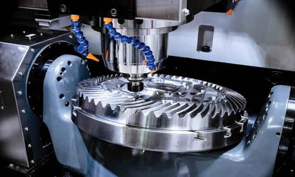
A laser pointed at the face of a turned part will read a change when the part is taller. It will also read a change if a chip lifts the part in its nest. The two readings can look the same on a display. That is the main design problem in a quick height check after turning a spacer, sleeve or similar component.
Decide what the measurement is relative to
Start with the dimension on the drawing. If the feature height is specified from the seating face, the inspection station must reproduce or observe that face. A sensor mounted above the part sees its distance to the spot it illuminates. Converting that reading into part height requires a known relationship between the sensor and the datum. A nest that never quite seats the part can make an otherwise sound measurement process misleading.
Consider a simple commissioning exercise with a reference part. First compare repeated readings without moving it. Then unload and reload it several times. If the readings spread after reloading, investigate seating, dirt and fixture movement before chasing sensor settings. For a measurement that needs to separate actual part height from seating errors, consider an independent reference to the relevant datum and compare the two readings in a defined fixture geometry.
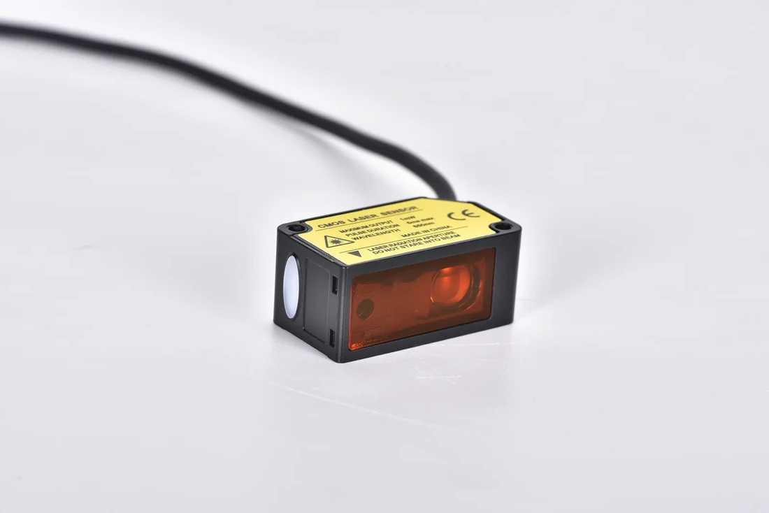
LK-F laser displacement sensor front and side view
Choose where the spot lands
The corner of a machined chamfer is a poor substitute for the face named on the drawing. Leave room for lateral part movement so the spot stays on the intended flat. A worn locator or a different tool finish can bring an edge, oil film or polished ring into the spot. Include the surfaces that production will actually make when you compare readings.
The LK-F displacement sensor model table gives reference distances and measuring windows for several configurations. A window is the space over which the sensor can take measurements. It is not the amount by which a part is allowed to vary. Check that both the nominal face and the full expected movement fit. The M models offer an analog measurement output if the controller needs to record a value alongside a switching signal.
Make a useful decision from the result
Write down how the station handles a valid height, a value outside tolerance and a missing reading. For example, a part whose reference face is not seated should go through the defined inspection exception process. Treating the last good sensor value as this part’s height can quietly pass an unmeasured part.
If access to the datum forces an awkward mounting angle or a different standoff, the laser displacement sensor range is a place to compare other arrangements. Provide the supplier with a section drawing showing the datum, the illuminated face and the real clearance around it. That drawing is more informative than an isolated tolerance figure.
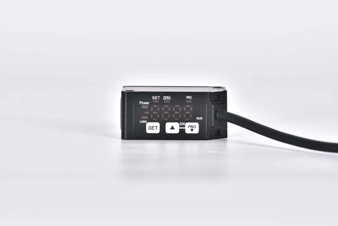
LK-F display and control keys
